
Home
Aviation Stories
"In Memory Of"
Net Sites
Sign Guestbook
View Guestbook
Email Ron

Aircraft Charging Systems
Understanding and troubleshooting the alternator systemStory and Illustrations by Ron Kilber
FOR MANY of us, troubleshooting an alternator-system problem usually involves the shotgun approach. If a new battery doesn't cure the ailment, perhaps a new regulator, alternator or other component will. Murphy's law always prevailing, nine times out of ten, success arrives only after the last component in the system has been replaced.
By understanding the simplicity of the alternator design, troubleshooting can be a cakewalk for anyone who can at least figure out how to replace a burned-out light bulb. Not having to replace working components means it's easier, quicker and cheaper to get back in the air.
The modern alternator used on aircraft charging systems today ranks as one of the most important inventions in all of technological history. Few devices have been produced and used in greater number than the alternator, a marvelous little standalone dynamo that can output alternating current (AC) at levels to 100 volts and more. When used in a 12-volt charging system, for example, the alternator output is rectified (converted) to direct current (DC) using diodes, then clamped at approximately 14.2 volts with the aid of a voltage regulator.
Engine starting is the basic function of the battery, after which the alternator supplies continuous electrical power not only to all essential equipment on the airplane, but to recharge the battery as well.
The regulated voltage (14.2) to the system bus is somewhat higher than the battery voltage (12 volts) so that alternator current flows to the battery to charge it. If the regulated output were, say, only 11 volts, battery current would flow to the bus instead, eventually discharging it. So to keep a full charge, the regulator must clamp at something greater than 12 volts, but not so high as to boil the battery or damage onboard electrical equipment. Thus, 14.2 volts (+/- .4 volts) is the industry standard for charging systems using 12-volt batteries.
HISTORY
First gaining widespread use on automobiles in the mid sixties, the alternator became the de facto standard on virtually every engine-driven vehicle and machine -- including the airplane. Best known for its ability to produce output at low engine revolutions, the alternator replaced its predecessor, the DC generator, which served well for many decades, but at a tremendous performance, weight and maintenance disadvantage.
The alternator design isn't only characterized by exceptional simplicity, it's also an extraordinarily reliable device. Without getting too technical, there is only one moving part: the field winding rotating with a single shaft. Electrical output is derived not by carbon brushes (as with the obsolete DC generator) but by a direct electrical connection to a stationary armature (stator). With the exception of the solid-state rectifier (diodes), the only thing between the output and the load is a wire, making for an incredibly ingenious system, both simple and reliable. It can work trouble-free for decades. The cost of a nonaircraft alternator is about the price of a dinner for two.
ALTERNATOR THEORY
Figure 1 shows the principle of alternating-current generation. It consists of a rotating field magnet (for simplicity I show a bar magnet) and a pair of stationary poles (the stator). As the engine turns the alternator shaft (by belt or gear drive), the magnetic field induces a voltage in the stator. Voilà! Out of thin air there's electricity.
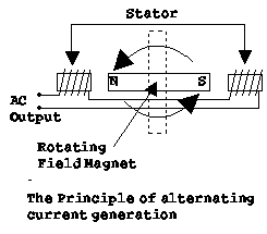
Because the rotating magnet induces voltage via its "north pole" into the stator winding first, then via its "south pole", the alternator produces alternating current. In other words, the current flows first in one direction from the output, then reverses and flows the other way. Like gravity and so many other mysteries of the universe, few understand exactly how this induction process works; it just does.
Most airplane and automobile charging systems use direct current. However, thanks to the invention of the rectifier, there's no problem or big expense converting AC current to DC.
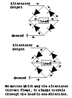
The rectifier (or diode -- the solid-state variant of the obsolete vacuum tube) allows current to flow to the output in only one direction. When configured in an array as illustrated in Figure 2, AC current ends up as DC. So no matter which way the current flows into the rectifier, it always exits in a single direction. Like fire exits on buildings, current is forced to enter the front door to get out the back. Likewise, current can't enter the fire exit; it must use only the front door. Diode arrays are an ingenious design, extremely reliable when used within operating and environmental design specifications.
PRACTICAL THEORY
Of course, the previous example doesn't provide any way to control or vary the alternator's output, short of changing the size of the magnet or adjusting the engine rpm -- both of which aren't practical solutions while the pilot is trying to maintain airspeed or altitude.
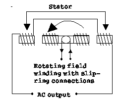
So if we replace the bar magnet with a coil of wire, we end up with an electromagnet wherein the strength of the rotating field can be changed by simply varying the current flowing through it (by low-amperage slip rings and carbon brushes). Like a rheostat changing the intensity of panel lights, the output level of any alternator can be adjusted by simply varying the electrical energy to the field winding. Just as a sound amplifier requires only a slight input from a microphone to power the speakers, the alternator's current output is much greater than what is needed to drive the field winding. The gain, of course, is robbed from the engine driving the alternator shaft.
Luckily, there is no need for a rheostat on the aircraft panel to control alternator output, although installing one certainly could do the job. The only problem is that the pilot would have to make constant adjustments as the electrical load varied the demand on the alternator.
The voltage regulator was designed to perform this tedious, never-ending job of controlling the amount of current to the field winding. It's an autopilot for bus voltage. The voltage regulator senses when the electrical system needs more current, responding in kind with more current flow to the field winding. In turn, the high-output stator produces more electrical current for the bus. The complete voltage-regulation process is entirely automatic, requiring no pilot intervention whatsoever.
Modern charging systems are remarkably reliable. Apart from the alternator shaft bearings, the only moving parts are two small carbon brushes riding on slip rings, which provide a means to energize the rotating field winding. Unlike the obsolete generator, these brushes carry only a small amount of current, making for a long-lasting, trouble-free electromechanical charging device.
Additionally, alternators have evolved into designs with multiple poles and field windings, which effectively produces AC output at much higher frequency than used in homes. We'll never, for example, hear a 60-cycle hum that has origin from the aircraft bus.
The only negative characteristic of some charging-system designs is that the field winding must be energized before there can be any usable output. With these systems, the alternator can't excite itself because there's no usable stator output until there's sufficient current to the field first. The battery solves this problem. Once the alternator supplies current to the bus, the battery is no longer needed for continued output. Just as the battery is needed to start the engine, it's needed to start the alternator too. Other designs, such as found on Piper and Cessna 24-volt systems, are capable of self-excitation without the battery. Something to think about when soup flying (when IFR gear is totally dependent on bus power).
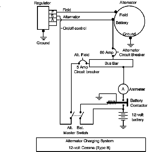
The regulator design is every bit as straight forward as any light-dimmer switch on a wall. In the example, the regulator's sole source of power is derived from the aircraft bus bar via terminal "A" and chassis ground. As bus voltage declines, such as when the landing light is turned on, the regulator senses the deficit and increases the output to terminal "F", which is hard-wired directly to the alternator's field winding to produce more output. Thus, like a teetertotter, when the voltage recedes on terminal "A" (bus), the current increases on terminal "F" (field).
Likewise, when the bus has sufficient voltage, the regulator dampens alternator output with less energy to the field winding. No matter what fluctuations occur on the aircraft bus, the regulator is continuously working to maintain constant voltage (e.g. 14.2 volts).
Also, when the pilot makes throttle adjustments, the regulator must compensate for the new rpm, which directly vary the alternator's output. When landing at night, for example, as the engine power is reduced, the alternator output will dampen. Instantly, the regulator responds with more current to the field, which in effect enables the alternator to maintain the same output (and landing-light intensity) with fewer rpm.
ADVANCED REGULATING SYSTEM DESIGNS
When the charging system malfunctions, say, wherein the regulator develops a short that causes the alternator to put out maximum current and voltage (e.g. 100 volts), the avionics stack would be at great risk for expensive damage. This situation can be easily guarded against with the use of an over-voltage sensor (OVS) and cutout relay. Installing an OVS between the bus and terminal "S" of the regulator solves this problem. In other words, whenever the bus voltage goes too high, as it would with a runaway alternator, the OVS senses the problem, then opens the circuit to the regulator (terminal "S"). In turn, the regulator's built-in cutout relay responds by interrupting energy to the field winding (via terminal "F"), effectively shutting down the alternator.
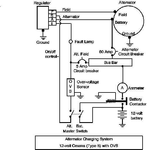
The process is not unlike a tripped circuit breaker (CB) rendering a wall switch and light inoperable (though CBs trip from too much current, not too much voltage). At any rate, automatic shut-down of a runaway alternator can prevent expensive damage to the avionics, not to mention the battery, which in most cases would have sufficient remaining energy to aid safe landing of the aircraft.
Besides the OVS, the split master switch (two switches in one) provides a manual means to shut down the charging system. The alternator half of the switch, like the OVS, is also in series with the bus and terminal "S" of the regulator. In other words, opening this switch shuts down the alternator -- the same as the OVS does when there's too much voltage on the bus. Unlike a single-pole master switch on the panel, the split switch provides the pilot with the ability to shut down the charging system at will, while maintaining bus voltage with the battery alone.
The alternator "fault" lamp on the panel illuminates whenever the regulator is shut down, either by action of the OVS or the alternator-side of the master switch. The lamp is referred to mean "low voltage", "overvoltage" or "low/over voltage", many times interchanged from one model to another by the same manufacturer. The fault lamp is powered by bus voltage and terminal "I", which goes to ground when the regulator is shut down. If cycling the master switch does not turn the fault indicator off, it's time to land and troubleshoot. It's always a good idea before flight to check the fault lamp, which illuminates whenever the alternator half of the master switch is turned off (battery side on).
Another safety feature gaining popularity is the field-short protection circuit. Electrical shorts can develop when abrasion, for example, wears insulation to the point where bare wire makes contact with the shield ground or the aircraft chassis. When this occurs on the wire to the field winding, the short can damage the regulator for good, rendering the alternator useless. To guard against field shorts, some regulators have built-in field-short protection.
It's surprising that there are many aircraft today operating without OVS and split-master protection. Fortunately, some regulator manufacturers offer built-in OVS protection, which requires no modification except for removal of the OVS or installation of a panel lamp connected to terminal "I" of the regulator. Also, converting to a spilt-master switch isn't all that expensive or complicated.
Of course, adding more technology like OVS increases the likelihood for more failure points in the chain, but the tradeoff for protecting expensive avionics is well worth it. Some OVS circuits (Cessna) are designed to open-circuit when failed, effectively shutting down the alternator. Others (older WICO) will fail in the closed-circuit condition, effectively negating their usefulness.
TROUBLESHOOTING ALTERNATOR SYSTEMS
(Refer to the previous figure 5)
Whenever there's a charging-system problem, there are a few basics that must be checked. First, the battery must be in good condition, ready to at least start the engine.
Second, a good, sensitive ohm meter must be used to check the condition of the field winding (an inexpensive ohm meter can't accurately measure four ohms). This is done by disconnecting the regulator (with engine and master off, both sides) and placing one lead of the ohm meter to ground, the other to pin "F" of the connector, which joins the wire to the alternator's field. If it's a dead short (zero ohms), it will cause a frequent problem with malfunctioning systems: a broke voltage regulator (shorted main transistor). The system works only momentarily, then shuts down or overcharges all the time. The voltage regulator and the shorted alternator must be replaced or overhauled.
Field resistance should never be less than four ohms and must be checked by rotating the propeller to include measurement while the brushes rotate 360 degrees around the slip rings. If the resistance is too high or fluctuates too much as the shaft rotates, the brushes or slip rings could be defective. The alternator will charge very little or not at all.
With infinite resistance, on the other hand, the field winding could be open (broke) or the wire to the alternator is loose or off. The system will not charge at all. Improper field resistance usually indicates that a new or overhauled alternator is needed.
Third, a few simple voltage checks can be made to isolate elusive problems (with the regulator reconnected). Terminal "A" of the regulator should always read 12 volts whenever the master switch is on (with or without the engine running or alternator half of the master on). Because this terminal is hard-wired to the bus, its voltage will read whatever is on the system. If, for example, the battery is dead, the reading on terminal "A" of the regulator (provided at least the battery side of the master is on) will be also.
The charging system will not work unless the regulator is enabled by terminal "S". If there isn't bus or 12 volts on terminal "S" of the regulator (both sides of master on, engine off), either the OVS sensor is defective or the fuse or circuit breaker before it is open. Of course, a broke master switch could be the problem too, preventing bus voltage from reaching terminal "S".
Terminal "F" of the regulator should read 0 volts when the alternator side of the master switch is off (battery side on, engine off). This is intuitive, the same way any wall switch turns the light off.
With both sides of the master on (engine off), Terminal "F" should have output for the field winding, making the alternator ready to produce 14.2 volts when the engine runs.
The state of terminal "I" determines whether the fault lamp is on or off. If it's approximately zero volts (such as when the alternator side of the master is off), the fault lamp will illuminate, indicating that, indeed, the regulator is disabled or shut down. If terminal "I" is bus voltage (alternator side of master on), the lamp will be off, indicating the regulator is turned on.
The fault lamp can be checked by grounding terminal "I" manually. If it does not illuminate, it's burnt out. An illuminated fault lamp (both sides of the master on) suggests the regulator has malfunctioned. Of course, the remainder of the regulator could still function sufficiently to make the charging system work as designed.
RUNAWAY ALTERNATOR
I recently had a problem with my Cessna 150 charging system. With the engine running and the master switch off (both sides), I still had power to the bus. I could turn the lights and avionics on, even run the flaps. No matter what I did with the master switch, power always remained on the bus.
It wasn't until I disconnected the field wire to the alternator that the problem was cured. Of course, this left only the battery to power the bus. In other words, my voltage regulator was outputting on terminal "F" when it wasn't suppose to, effectively energizing the alternator field with current -- a runaway alternator. Luckily, the engine was only at idle, preventing the alternator from putting out enough voltage to damage anything. Replacing the defective regulator solved the problem.
This interesting problem has taught me not only a valuable lesson, but another good preflight check too. Prior to any flight now, I always momentarily turn my master switch off (both sides). If power remains on the bus, I won't go flying.
Worse, there's no manual method to shut down a runaway alternator during flight when the master switch fails the task. You have to disconnect the field or battery wire to the alternator, which means you must land to get under the hood. Meanwhile, anything powered by the bus is subject to damage by high voltage. Light bulbs, indicators and avionics could burn out. The battery, however, can be spared a cooking, provided the main contactor is open (master switch off).
Also, such an occurrence begs the question: What have designers done to prevent a malfunctioning voltage regulator from full-tilting an alternator? Nothing. And for good reason. If a panel-mounted switch, for example, enabled the pilot to manually remove energy to the field winding, other problems would enter the picture. Abruptly interrupting field current causes the windings of the alternator to produce an "inductive kickback" high enough to ruin solid-state electronics. A loose or dirty connection can cause the same problem.
If the panel-mounted switch were used instead to manually remove power to the entire regulator (terminal A), it would introduce contact resistance, voltage fluctuations and ammeter flicker into the system. It's better to have a stable, reliable design than to find ways from facing the music when an alternator runs away.
DIFFERENT VOLTS FOR DIFFERENT FOLKS
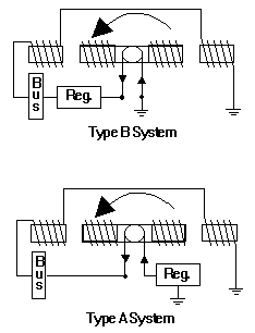
So far, we've focused entirely on the "Type B" charging system used in Cessna 12-volt designs. This setup is characterized by placing the voltage regulator between bus power and the alternator field. In this way, the regulator meters bus current to one side of the field winding, while the other side is permanently grounded at the alternator.
The "Type A" design, such as used in the older Grumman 12-volt system, is characterized by placing the voltage regulator between the field winding and ground. In this way, the regulator meters bus current to one side of the field winding, while the other side is permanently connected to the bus.
Each of these systems produces different challenges. For example, a "Type A" ground short on the field wire to the alternator will force it to run away, producing maximum output.
Conversely, a "Type B" ground short on the field lead to the alternator will simply shut it down. To get a run-away alternator, you need a bus-to-field short (very unlikely) or a defective voltage regulator (such as my Cessna 150 problem).
Few industries strive to keep things simple or compatible. Piper's 12-volt system is different from Cessna's. Newer designs incorporate the voltage regulator inside the alternator. And many aircraft today incorporate 24-volt systems, all of which makes for confusion and difficulty for mechanics who work from one design to the next.
There isn't room here to discuss every single charging-system design in detail. Instead, we've just covered the basics of aircraft charging systems. Once we learn the charging system, it's easy to understand exactly how our specific design really works. And when things do go wrong with the charging system, success will arrive without having to shotgun or replace all components in the system.
###
© Copyright (C) 2000 Ron Kilber All rights reserved. rpknet@aztec.asu.edu RonKilber.tripod.com Non-commercial reproduction permitted in its entirety with this copyright notice intact.